RAK PoE Node
In this guide, I will go over the process of how I built my PoE-powered Meshtastic base station. This is an easy to build node that uses primairly official RAK components, so no soldering is required!
Parts list
Most of the parts for this build were purchased from Rokland. I highly recommend buying Meshtastic parts from Rokland where you can as they are absolutely great to work with.
- RAK Meshtastic Starter Kit
- ALFA Network Outdoor 915MHz LoRa antenna
- UFL/IPEX to N-Female connector
- RAK13800 Ethernet module
- RAK19018 PoE module
- Waterproof box
- Monoprice CAT6A cables
- RJ45 cable glands
Optional, if you don’t have a PoE switch:
You’ll also want to 3D print a mounting plate. I used the RAK19007 Mounting Plate by KBOX Labs.
Build guide
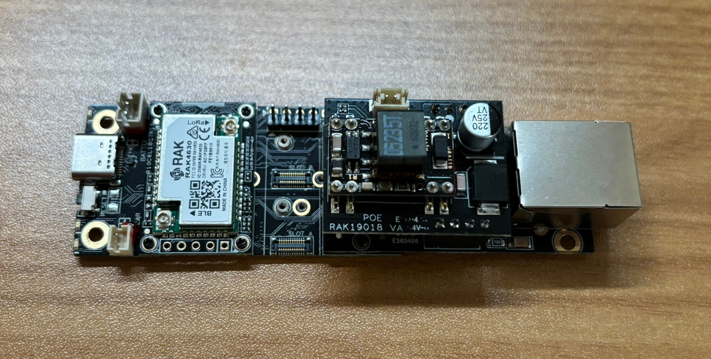
The first step is to assemble the RAK board. Installing the Ethernet and PoE modules is quite easy. The ethernet module simply screws into the RAK starter kit board, and the PoE module plugs right into the Ethernet module. I then proceeded to flash Meshtastic on the board and configure it to connect to my network using DHCP and uplink/downlink to the Iowa Mesh MQTT server.
I highly recommend testing out the PoE functionality at this time, as there are reports of issues with this PoE module when paired with some switches due to the low power consumption of the RAK board. If you run into any issues, disabling PoE power saving features on the switchport can help. If you are still running into issues, I recommend using an 802.3af PoE injector to power your node.
Now that the board is configured, we are ready to start building the rest of the PoE node!
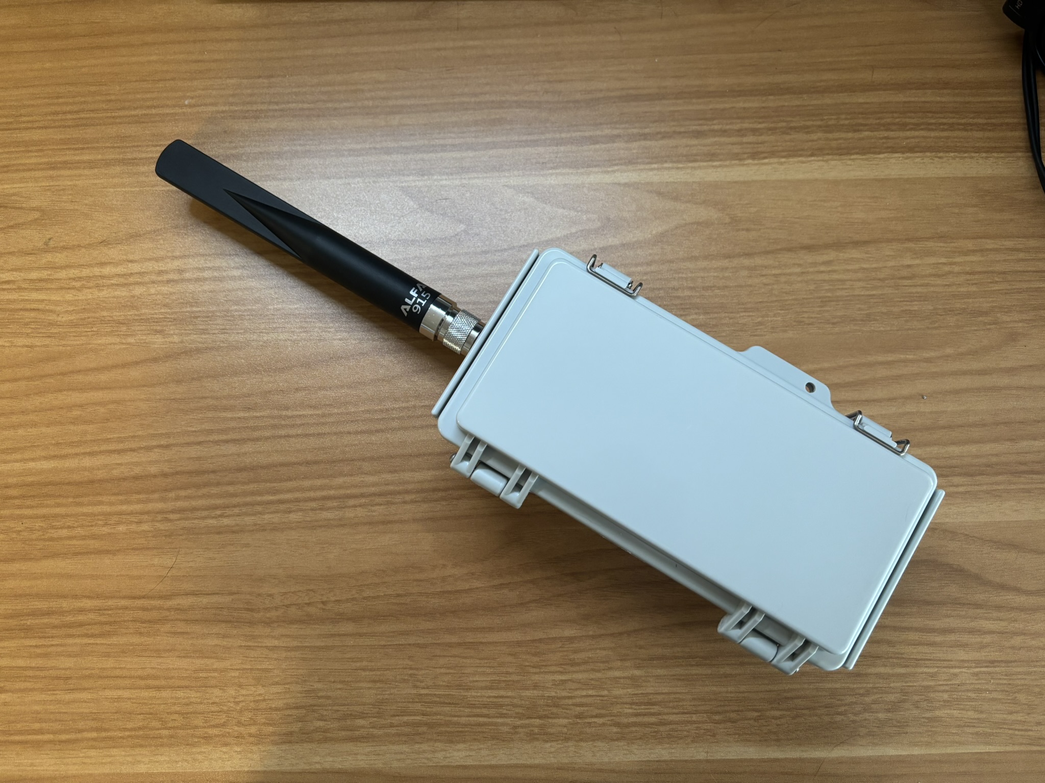
Using a step bit, I drilled a 5/8ths size hole on the top of the waterproof box for the antenna. I then screwed in the antenna, ensuring that the gasket built into the connector was touching the plastic box with no washers in front.
Next, I drilled a hole on the bottom of the box for the RJ45 cable gland using a step bit. If I was to do it all over again, I wouldn’t have centered this on the bottom of the box. If you ever need to remove the 5x5 grid, it’s in the way of the screws.
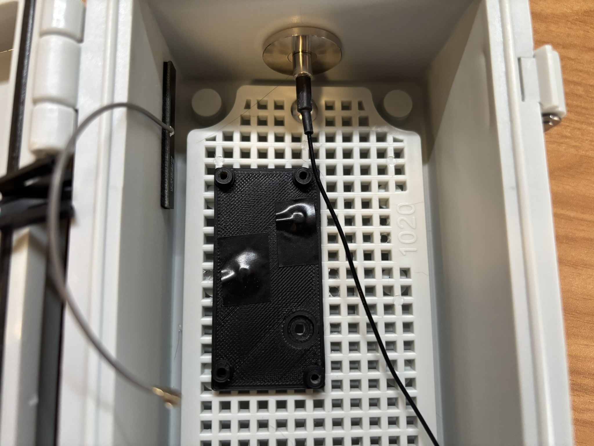
After installing the antenna connector and RJ45 cable gland, I screwed in the 3D-printed RAK mounting plate. I only screwed in two screws here, as I had soldered on some pin headers for a BME280 temperature, humidity, and barometric pressure sensor. I used some 3mm-0.5x6mm screws from Menards here. I placed electrical tape over the screws as I wasn’t able to find flat head ones.
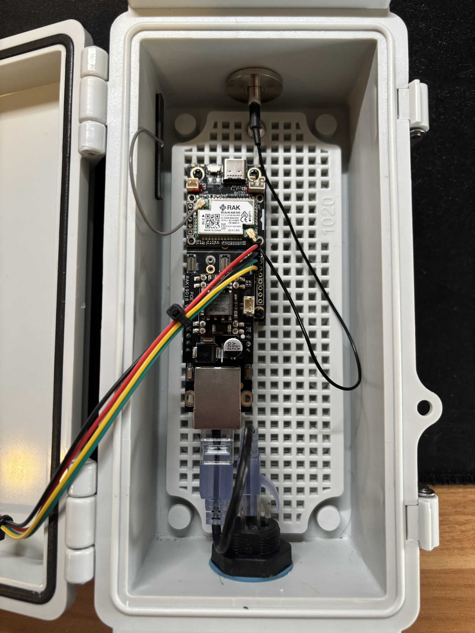
Finally, I screwed the RAK board into the 3D-printed mounting plate and connected the LoRa and Bluetooth antenas, and the Ethernet cables to the Ethernet board.
Below is a picture of the inside of the finished node. One addition I made was adding a BME280 environmental sensor which is connected to the RAK board through the I2C headers. I chose to use an external sensor since I was afraid the PoE module would throw off the readings, but it doesn’t seem to do so. If you wish to add enviornmental monitoring to your node, the official RAK sensor board would probably suffice.